
This is in continuation of Atmega328-Arduino Uno . It provides information on Arduino UNO Reset.
In last blog, I verified the factory programmed boot loader start section was 0x7E00 ( i.e. 0x3F00 <<1) . One of the important aspect of any embedded program is to understand the program flow after RESET.
Is it possible to configure RESET vector at Application Start Section in flash ?
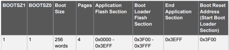
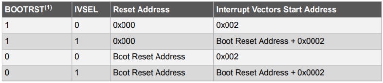
Yes, We have flexibility to use either Application section(0x0000) or Boot Reset Address defined by boot loader parameters BOOTSZ1,BOOTSZ0 (0x7E00) as Reset Vector address. We noted hfuse byte = 0xDE in the last experiment. i.e. BOOTRST=0 . So as per following table Reset Address should be Boot Reset Address 0x7E00
Q: If Reset Vector Address is configured to boot from 0x7E00, How my application boots every time after Power-ON RESET ?
Lets validate above with boot loader list file optiboot_atmega328.lst from optiboot folder C:\Program Files (x86)\Arduino\hardware\arduino\avr\bootloaders\optiboot
- int main(void) {7e00: 11 24 eor r1, r1#ifdef __AVR_ATmega8__ //Not Relevant SP=RAMEND; // This is done by hardware reset#endif// Adaboot no-wait mod
ch = MCUSR;
7e02: 84 b7 in r24, 0x34 ; 52
MCUSR = 0; // We will be not able to check the original MCUSR at RESET later
7e04: 14 be out 0x34, r1 ; 52
if (!(ch & _BV(EXTRF))) appStart(); //External Reset Flag
7e06: 81 ff sbrs r24, 1
7e08: f0d0rcall .+480 ; 0x7fea
What appStart() does ?
- void appStart() {watchdogConfig(WATCHDOG_OFF);7fea: 80 e0 ldi r24, 0x00 ; 0 //appStart() is defined in boot loader section7fec: e8 df rcall .-48 ; 0x7fbe__asm__ __volatile__ (
7fee: ee 27 eor r30, r30 //Exclusive OR i.e clear r30
7ff0: ff 27 eor r31, r31 //Exclusive OR i.e clear r30
7ff2: 09 94 ijmp //Indirect Jump to address set in Z register(R31:R30)
EXTRF is the part of MCUSR register description given below :
What RESET Options are available with this MCU?
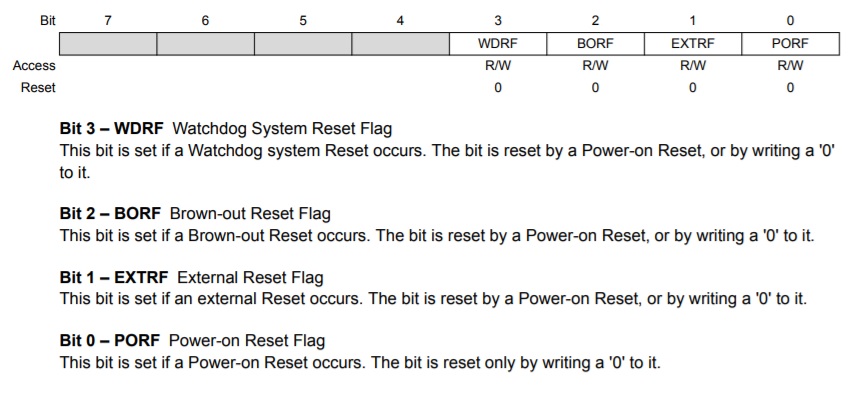
When EXTRF will be set ?
External Reset. The MCU is Reset when a low-level is present on the RESET pin for longer than the minimum pulse length. There is a provision of RESET push button in Arduino Uno board.
This clarifies the application start at Power-ON RESET and boot loader start after pressing the RESET push button on the board. This is the reason that pressing RESET is advisable if some issue in communicating with the board .
Q: But how application starts after some time even after pressing RESET button to start boot loader.
Ans: This is because of Watchdog is enabled in optiboot and Only a continuous communication from USART will keep kicking this Watchdog timer. If there is no data for some pre-defined time(one sec) , Watchdog reset will occur and optiboot will jump to appStart() , disable WatchDog and continue from Application Start Section 0x0.
Note: The Watchdog timer value 10000 is just an example in YouTube discussion, I will post another article for Watchdog related settings.
References
All documents are available here. I am referring to most of these :
- Arduino Programming notebook
- Inline Assembler cookbook
- AVR Instruction set reference manual
- ATmega328P datasheet
- ATmega328P datasheet -Automotive version
- Arduino Uno board schematic
- HowOptiBootWorks
This article is discussed at Atmega328-Arduino Uno Part 2 video.
Thanks for reading till end. I am trying to improve usability of my site. Did you find this discussion helpful ? If so, Please subscribe to YouTube channel Embedkari as well for additional embedded related stuff.