
This is in continuation of last blog. I will validate the ATmega328P concepts with practical approach.
How ATmega328P Peripherals are mapped in Memory?

Which AVR core is used in ATmega328P ?
ATmega328P name implies that it is from megaAVR family of AVR core series. This precise information is required to understand instructions supported in this device.
Why there is a need to learn Assembly when we have C++ based Library ?
I will not recommend any hobbyist to do into in-depth assembly because that will nullify whole concept of Arduino. However there is no harm in spending some time to understand the importance of Assembly. Here are some basic points
- High level language like C depends on Assembly for creating basic stack. You may find some information on video C Learning Tips with x86 platform
- Assembly is helpful for designing optimized time critical functions
- Assembly is helpful in understanding MCU architecture better because C is architecture independent language
- Additional skill set for Engineering students interested in embedded domain
Is Learning assembly a tough job ?
Not at all, It’s not a rocket science. For RISC based architecture, You need mechanism:
- To read(load) from a memory or memory mapped I/O
- To write(store) to a memory or memory mapped I/O
- To change program flow(branch) with or without a condition
- To perform arithmetical and logical operations.
Examples for decoding AVR Assembly Code :
I wrote a simple C code to display basic GPIO ports and analyzed the disassembly of the same. The method to fetch assembly from executable file was discussed in blog.
Reading GPIO using Indirect Addressing :
- dump_GPIO_registers() //From sample C code
You will notice that the disassembly file has a mixture of 16 and 32-bit instructions.
16-bit Instruction decoding
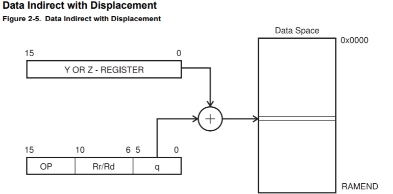
41a: 8b a1 ldd r24, Y+35 ; 0x23
- LD (LDD) – Load Indirect from Data Space to Register using Index Y
- LDD Rd, Y+q 0 ≤ d ≤ 31, 0 ≤ q ≤ 63 //From Datasheet
- d=24=0x18 =0001_1000 //From instruction line given above
- q=35=0x23 = 0010_0011 //6 bits to address 64 I/O addresses
- Opcode Explanation
- Note the sequence of d and q bits in the opcode below with color coding
- opcode format : 10q0 qq0d dddd 1qqq //From Data Sheet
- 1010_0001_1000_1011 =0xA1_8B //Match with disassembly code
- //after changing byte order
- Here is the logic explained in datasheet
32-bit Instruction decoding
Lets analyze a 32-bit instruction/opcode in the same code listing
- 41c: 0e 94 b3 01 call 0x366 ; 0x366 <_ZN5Print7printlnEhi.constprop.7>
- CALL k 0 ≤ k < 64K PC ← k Devices with 16-bit PC
- opcode format 1001 010k kkkk 111k kkkk kkkk kkkk kkkk
- K = 0x366=0000_0011_0110_0110 (shift right 1) ->0000_0001_1011_0011
- Note: shift right is done above because opcode will have word addr
- 1001_0100_0000_1110_0000_0001_1011_0011 = 0x940E_01B3
- 14 bit PC for 16K range
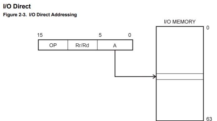
16 bit I/O specific instruction
- OUT – Store Register to I/O Location
- 4c2: 0f be out 0x3f, r0 ; 63
- OUT A,Rr 0 ≤ r ≤ 31, 0 ≤ A ≤ 63
- 1011 1AAr rrrr AAAA // Note: 6-bit I/O address can cover 64 I/O addresses
- A=0x3F=11_1111
- r=0x00 = 0_0000
- 1011 1110_0000_1111 = 0xBE_0F
Can we analyze assembly of PORTB reading ?
-
-
- As per Register Summary PortB is at 0x23
- IN – Load an I/O Location to Register
- IN Rd,A 0 ≤ d ≤ 31, 0 ≤ A ≤ 63
- 1011 0AAd dddd AAAA
- 83 b1 in r24, 0x03
- d=24 = 0x18=0001_1000
- A=0x03=0x0000_0011 //Subtract 0x20 in I/O specific command
- 1011 0001_1000_0011 =0xB1_83
-
- The extended I/O memory from address 64 to 255 can only be reached by data addressing, not I/O addressing.
Exercise to be completed :
One can understand this concept better by repeating the exercise > Hope you can decode the following long jump instruction discussed in last blog
- 7fee: ee 27 eor r30, r30 //Exclusive OR i.e clear r307ff0: ff 27 eor r31, r31 //Exclusive OR i.e clear r307ff2: 09 94 ijmp //Indirect Jump to address set in Z register(R31:R30)
References : All documents are available here. I am referring to most of these :
- Arduino Programming notebook
- Inline Assembler cookbook
- AVR Instruction set reference manual
- ATmega328P datasheet
- ATmega328P datasheet -Automotive version
- Arduino Uno board schematic
To understand the data addressing better , We can look into section The Program and Data Addressing Modes of AVR Instruction set reference manual
Here are few other interesting topics @Embedkari
How to choose sensor, processing device and network for IoT ?
How I can practice AVR, ARM, Linux and other Embedded Questions for Interview ?
This article is discussed at ATMega328 Ports Mapping.
Thanks for reading till end. Please provide your feedback regarding this article. Also subscribe Embedkari for other interesting topics. .
Thanks for reading till end. I am trying to improve usability of my site. Did you find this discussion helpful ? If so, Please subscribe to YouTube channel Embedkari as well for additional embedded related stuff.