
Prerequisite : Basic knowledge of C++ is required to understand the program, Otherwise anyone can complete the steps here. This particular blog post is for students and hobbyist interested in c++ embedded use case and exploring different low cost projects. This is in continuation with previous blog about Arduino C++ Library.
Ultrasonic Range Module : The ultrasonic range module HC-SR04 datasheet provides information about basic principle and connections. This module should not be connected to already powered circuit i.e Avoid hot-plug as a precaution. There are reports of faulty modules so it is always better to take precaution. Also identify a genuine vendor for such products. You may find direct link to vendor from HC-SR04 image on my blog home page.
Step 1: Make sure Arduino Uno board is not powered. Connect Arduino Uno to HC-SR04 as per instructions given below :
There are only four signals(VCC,GND,Trigger,Echo) to be connected from Ultrasonic Range Module HC-SR04 to Arduino UNO, So You may utilize breadboard.
- Arduino PIN 12 tied to TRIGGER pin on the ultrasonic sensor.
- Arduino PIN 11 tied to ECHO pin on the ultrasonic sensor.
- Arduino Power GND tied to GND pin on the ultrasonic sensor.
- Arduino Power 5V tied to VCC pin on the ultrasonic sensor.
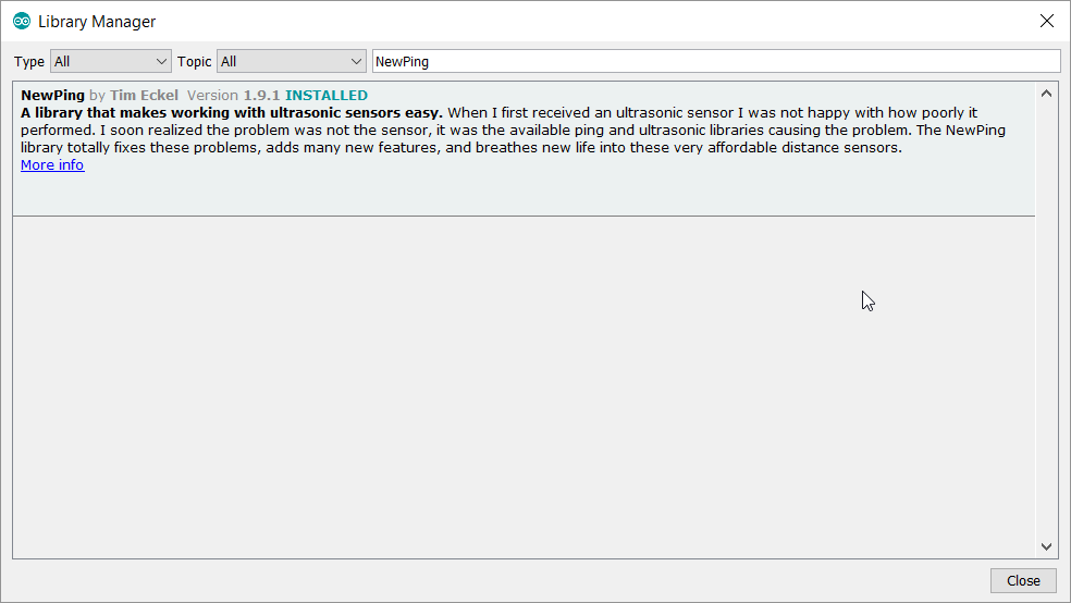
Step 2: Installation of NewPing Library
Click on Arduino IDE Sketch->Include Library->Manage Libraries . If it shows installed as given below, Move to next step or Install it first.
Step 3: Click on File->Examples->NewPing->NewPingExample

Step 4: Make sure the GPIO numbers shown in the file match with the connection

Step 5: Click on Verify below File to compile

Step 6: Connect Aurduino UNO USB cable to laptop/PC where IDE is installed and Check the COMM port selection. As discussed in earlier post, You may verify Port in your System->Device Manager first.

Step 7: Click on Upload and wait till you get Done Uploading message
Step 8: Open Tools -> Serial Monitor . Make sure that baudrate matches with the Serial.begin() in setup(). Here it is 115200. Now bring any object in front of HC-SR04 module and notice the change in distance being printed. Here is one demo :

Step 9: After verification of data in serial monitor, We can plot it as well. Plotter Y axis works on the value passed by Serial.println() .
- Change default Serial.print(sonar.ping_cm()) to Serial.println(sonar.ping_cm(),DEC)
- Here DEC is for decimal format
- Close serial monitor and open Tools->Serial Plotter . Make sure you have same baudrate selected as in serial monitor
- Here is the demo. The curve goes down whenever I take any object near HC-SR04.

Step 10: Now we can test this without connecting to laptop i.e. Independent mode. I utilized built-in LED to glow whenever object comes to less than 10cm. The global variable state is used to make sure LED ON/OFF happens only after stable state. This is similar to software debouncing for key press action. You may try by changing ENTER_HUNT and EXIT_HUNT constants for faster response time.
#define ENTER_HUNT 10
#define EXIT_HUNT 20
unsigned int state;
void setup() {
Serial.begin(115200); // Open serial monitor at 115200 baud to see ping results.
pinMode(LED_BUILTIN, OUTPUT); //Set port 13 as output to use Builtin LED
state=0;
}
void loop() {
int dist;
delay(50);
dist=sonar.ping_cm();// Wait 50ms between pings (about 20 pings/sec). 29ms …
Serial.print(“Ping: “);
Serial.println(dist,DEC); // Send ping, get distance in cm and print result (0 = outside //set distance range)
Serial.println(“cm”);
if ((dist >0) && (dist <10))
{
if (state >EXIT_HUNT) digitalWrite(LED_BUILTIN, HIGH);
else state++;
}
else {
if (state <ENTER_HUNT)
digitalWrite(LED_BUILTIN, LOW);
else
state–;
}
Serial.println(state);
} //End loop

Thanks for reading till end. I am trying to improve usability of my site. Did you find this discussion helpful ? If so, Please subscribe to YouTube channel Embedkari as well for additional embedded related stuff.