
In this blog, I will discuss minimal programming required for ADC block . This may help embedded beginners to understand implementation of ADC in Arduino Board using C.
This is in continuation with my last blog post. I strongly recommend you to read earlier blogs for better understanding . If you find something missing, Please provide feedback in comment box so that I can take corrective action
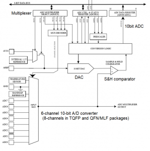
ADC Block
Step 1: Make sure ADC is not shut down
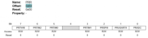
- Power Reduction ADC bit (PRR.PRADC) =0 to enable ADC

Step 2: Select reference voltage = AVcc(5V) and required analog pin from multiplexer
- ADC Multiplexer Selection register ADMUX.MUX[3:0] to select analog input channel
- Select VRef . The ADC count corresponding to VRef is 0x3FF (1023)
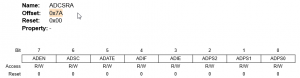
Step 3: Enable ADC logic using ADCSRA
- ADC Control and Status Register A (ADCSRA.ADEN).=1 to enable ADC
- Voltage reference and input channel selections will not take effect until ADEN is set
- The 10-bit result , ADCH and ADCL, is by default right adjusted. Set Left Adjust Result bit ADMUX.ADLAR =1 if left adjust is required.
Step 4: Start ADC conversion and wait for its completion
- A single conversion is started by setting PRADC=0 and ADC Start Conversion bit, ADSC=1. ADSC will be cleared by hardware when the conversion is completed.
Tested Code
//Define required pins and important registers
int pin_A0=14;
int pin_A1=15;
#define mPRR (*(volatile uint8_t *)0x64)
#define mADCSRA (*(volatile uint8_t *)0x7A)
#define mADMUX (*(volatile uint8_t *)0x7C)
#define bitVal(bitNum) 1 << bitNum
#define VREF_DEFAULT 0x01
//We are using Serial and PinMode initialization from library. You may refer to earlier blogs //about these . Therefore , In this blog only ADC part will be explained
void setup() {
Serial.begin(115200);
pinMode(LED_BUILTIN, OUTPUT);
pinMode(pin_A0, INPUT);
pinMode(pin_A1, INPUT);
}
float analogPin(uint8_t chNo)
{
unsigned int data,tmpH,tmpL;
float avgADC;
float resultV;
data=0;
//Select VREF=01 default Vcc(5V) channel number
mADMUX= (VREF_DEFAULT <<6 ) | (chNo);
//Taking 100 sample reading just for experiment
for(int i=0;i<100;i++)
{
mADCSRA |= bitVal(ADSC); //start ADC conversion
//wait for ADSC flag to be cleared by hardware
while(mADCSRA & bitVal(ADSC));
tmpL = ADCL;
tmpH = ADCH;
data=data+((tmpH << 8)| (tmpL));
delay(10);
}
avgADC=(float)data/100; //average
//Calculate Analog voltage corresponding to data resultV= (avgADC*5)/1024;
return resultV;
}
void loop() {
Serial.print(“Input voltage at A0=”);
Serial.println(analogPin(0));
delay(5000);
Serial.print(“Input voltage at A1=”);
Serial.println(analogPin(1));
}
Output
I connected Pin14(A0) to ground and Pin15(A1) to a resister divider voltage=1.72V measured by Multimeter. Following is the giff file of output

This is discussed in this Embedkari video.
References : All documents are available here. I am referring to most of these :
- Arduino Programming notebook
- Inline Assembler cookbook
- AVR Instruction set reference manual
- ATmega328P datasheet
- ATmega328P datasheet -Automotive version
- Arduino Uno board schematic
Thanks for reading till end. Please provide your feedback regarding this article. Also subscribe Embedkari for other interesting topics. .
Thanks for reading till end. I am trying to improve usability of my site. Did you find this discussion helpful ? If so, Please subscribe to YouTube channel Embedkari as well for additional embedded related stuff.