


Before we go on to dig deep into the internal working of the Real time operating systems let us first go over some fundamental concepts one needs to understand to go about building their own RTOS. We are going to test and debug our custom RTOS on a Microcontroller and more specifically an ARM cortex-M microcontroller. Hence we also need to be aware of the features provided in the MCU (microcontroller unit). So let’s get started.
SOME BASIC OPERATING SYSTEM CONCEPTS
There are some fundamental concepts that every operating system in the world follows. And are equally important for Real time OS. Let’s take a look at some of the Fundamentals of operating systems:
1. Thread
Thread is a single unit of execution and is a part of a process. In a single core CPU which is common for microcontroller based embedded system there are applications which require you to perform multitasking. Each task you need to perform will be programmed in a single sequential flow. In like manner several such thread are coded to perform multiple tasks.
2. Task Scheduler
A task scheduler is a piece of code that decides which Thread/Task to run next. There are multiple methods you can use to decide which thread should be loaded and executed next. These ‘methods’ per se are called scheduling algorithms. A scheduling algorithm takes help from the Task Control block during it’s decision making process.
3. Context switching
The process of storing the state of the process in the memory so that it can be resumed later, is known as context switching. Performing context switching allows CPU to write multiple tasks simultaneously and is an essential part of a RTOS kernel.
4. Thread/task control block
A task control block (TCB) is a data structure used by kernels to maintain information about a task. To give a sense of a typical Task control block given below is the task control block of Micrium µC/OS-III.
struct os_tcb {
CPU_STK *StkPtr;
void *ExtPtr;
CPU_STK *StkLimitPtr;
OS_TCB *NextPtr;
OS_TCB *PrevPtr;
OS_TCB *TickNextPtr;
OS_TCB *TickPrevPtr;OS_CHAR *NamePtr;
CPU_STK *StkBasePtr;
OS_TLS TLS_Tbl[OS_CFG_TLS_TBL_SIZE] OS_TASK_PTR TaskEntryAddr;
void *TaskEntryArg;
OS_PEND_DATA *PendDataTblPtr;
OS_STATE PendOn;
OS_STATUS PendStatus;
OS_STATE TaskState;
OS_PRIO Prio;
CPU_STK_SIZE StkSize;
OS_OPT Opt;
OS_OBJ_QTY PendDataEntries;
CPU_TS TS;
OS_SEM_CTR SemCtr;
OS_TICK TickRemain;
OS_TICK TickCtrPrev;
OS_TICK TimeQuanta;
OS_TICK TimeQuantaCtr;
void *MsgPtr;
OS_MSG_SIZE MsgSize;
OS_MSG_Q MsgQ;
CPU_TS MsgQPendTime;
CPU_TS MsgQPendTimeMax;
OS_REG RegTbl[OS_TASK_REG_TBL_SIZE];
OS_FLAGS FlagsPend;
OS_FLAGS FlagsRdy;
OS_OPT FlagsOpt;
OS_NESTING_CTR SuspendCtr;
OS_CPU_USAGE CPUUsage;
OS_CPU_USAGE CPUUsageMax;
OS_CTX_SW_CTR CtxSwCtr;
CPU_TS CyclesDelta;
CPU_TS CyclesStart;
OS_CYCLES CyclesTotal;
OS_CYCLES CyclesTotalPrev;
CPU_TS SemPendTime;
CPU_TS SemPendTimeMax;
CPU_STK_SIZE StkUsed;
CPU_STK_SIZE StkFree;
CPU_TS IntDisTimeMax;
CPU SchedLockTimeMax;
OS_TCB DbgNextPtr;
OS_TCB DbgPrevPtr;
CPU_CHAR DbgNamePtr;
};
The above block controls all the information a scheduler will need to perform context switching.
5. Scheduling algorithms
The scheduling decision making process can be as simple as executing them one after the other (round Robin). The complexity of the scheduling methods depends on the application requirements. I have listed below some common scheduling methods for a real time kernel:
First-Come, First-Served (FCFS) Scheduling
First come first serve (FCFS) scheduling algorithm schedules the jobs according to their arrival time. The job which arrives first in the queue will get the CPU first.
Shortest-Job-Next (SJN) Scheduling
Shortest job next (SJN) is a scheduling policy that selects the process with the smallest execution time. This is a non-pre emptive method.
Priority Scheduling
Priority scheduling is a scheduling processes based on the task priority. In this method, the scheduler chooses the task to be executed next as per the priority.
Shortest Remaining Time
It is a scheduling method which uses the task completion time to decide its next task. This algorithm in a sense is a pre-emptive version of shortest-job-next algorithm. In this method the job with the shortest remaining time is executed first.
Rate monotonic Scheduling
It is a static priority assignment algorithm used in real- time operating systems (RTOS). These algorithm assigns the priority to the task according to their periodicity and run time. I.e. a task with lower periodicity is assigned a higher priority. Round Robin algorithm: is a pre-emptive algorithm and switches between the task one after the other in a circular fashion. This is the simplest scheduling algorithm.
6. Pre-emptive and Non Pre-emptive algorithm
Pre-emption refers to the temporary interruption and suspension of a task. The task are pre-empted because sometimes it is important to serve the higher priority task first. Therefore, the running task is interrupted and resumed later when the priority task has finished its execution. In non-pre-emptive scheduling, a task cannot be interrupted and is executed till its completion.
7. Semaphore
Semaphores are integer variables that are used to solve the critical section problem. They use wait and signal method for process synchronization. Wait and signal are atomic operations. First of all what are atomic operations? They are instructions which during their execution cannot be interrupted.
Next, what is the critical section problem?
The part of the program which tries to access any kind of shared resource is known as the critical section. These resources may be any resource in a computer like a memory location, Data structure or any IO device (UART, I2c, GPIO’s etc.). and the problem faced while two or more task tries to access the same resource , is known as critical section problem. So to avoid such kind of critical section problem , Semaphores are used as a signalling mechanism to notify the other thread that the resource is currently in use.
8. Inter process communication
Inter Process Communication (IPC) refers to a mechanism, where the operating systems allow various processes to communicate with each other. These can be done either by passing messages between the tasks or by using a shared memory.
9. CPU utilization
CPU utilization is used to estimate the system performance.it the amount of workload that is handled by the CPU. The goal of the operating system is to utilize 100% of the CPU capabilities although this is not practically achievable. CPU utilization can be calculated using a simple Formula.
U=(R/C)*100%
U= Utilization
R= BUSY TIME (the amount of time CPU is doing something)
C= BUSY TIME (the amount of time CPU is doing something) + IDLE TIME (the amount of time the CPU is not doing anything)
For eg:
BUSY TIME= R = 4576
BUSY TIME + IDLE TIME = C = 4567 + 2644 = 7211
CPU Utilization is
(4567/7211) * 100= 0.63 *100%= 63%.
—-Continue on Next Page
Which controller can I use that support RTOS?
A Scheduler can be written for most of the microcontrollers. Even the low end profiles such as 8051 can support RTOS (RTX51tiny, FreeRtos etc. have designed kernels for 8051). The choice of the MCU totally depends on the application requirement. But since we are building a kernel for ARM cortex-M profile of Microcontrollers we are going to focus our attention on the feature of cortex-m processors. ARM provides multiple OS support Features in their cortex-M profile using which the performance of the scheduler can be enhanced. Although we are not going to use all the features listed below but it is really important to have a basic understanding of these features.
So let’s take a look:
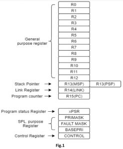

The above figure shows the register map of Cortex-M microcontroller [1].
There are 13 general purpose register <R0-R12> these are the register which the instructions will utilize for general execution . The register <R13> is the Stack pointer which points at the current location of the stack pointer in the memory. From the figure it can be observed that there are 2 different registers with the same name <R13>
• Main Stack Pointer (MSP): It is used by the operating system kernel, exception handlers and application codes that require privileged level access. This is the default stack pointer.
• Process Stack Pointer (PSP): This is used by the base-level application code (when not running an exception handler).
This is one of the OS support feature of ARM cortex-m i.e. this feature was added just so you can optimize and secure your operating system. This feature is known as Shadowed Stack pointer.
The <R14> link register which stores the address of the location where the program needs to jump whenever a branch with link instruction is executed. For example when you jump back from the function the return address is stored in the Link register.
The next is the program counter <R15> which stores the address of the current instruction which is being executed. Although this should be the case but in ARM cortex-m microcontroller a pipeline architecture is used hence the program counter is always pointing at the instruction ahead of the current executing instruction depending on the pipeline depth and structure.
There are 5 special purpose register known as the
PSRs (Program Status registers)
PRIMASK, FAULTMASK, and BASEPRI (The Interrupt Mask registers)
CONTROL (Control register)
Let’s see the operation and uses of each one of them.
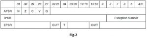
-The Program status register (PSRs)
This register is divided into 3 parts:
• Application Program Status register (APSR)
• Interrupt Program Status register (IPSR)
• Execution Program Status register (EPSR)
The three PSRs can be accessed together or separately using the special register access instructions known as MSR and MRS. When these register are accessed collectively, the name xPSR is used. PSRs can be read using the MRS instruction. You can also change the APSR register using the MSR instruction, but EPSR and IPSR are read-only.

(PRIMASK, FAULTMASK, and BASEPRI)
the Interrupt mask register. The PRIMASK and BASEPRI registers are useful for disabling interrupts temporarily for timing critical tasks. FAULTMASK can be used to Disable Fault handling temporarily and an OS can make use of this feature .
In a faulty scenario, a number of different faults might be taking place when a task crashes. Once the core starts cleaning up, it might not want to be interrupted by other faults caused by the crashed process. Therefore, the FAULTMASK gives the OS kernel time to deal with fault conditions.
The control register
The control register is used to define the Selections between the main Stack pointer and Process stack pointer and the privilege level. This register has 2 bits CONTROL[1] and CONTROL[0]. The CONTROL[1] is used to check the Stack Status i.e. one If the PSP is used and Zero if the MSP(default) is used.
The CONTROL[0] bit defines whether the privileged in thread mode(1) or user state in thread mode(0). Cortex-m provides two different operating mode i.e. the Thread mode and the Handler mode. And two different access mode known as the Privileged mode and User mode. This different kinds of mode help in providing security and reliability for example a program with only user level Privileges cannot access any special function register or control register and if it tries to do so a fault handler exception will occur.
A program running in Privileged mode can access all the special and control register and can switch the program between user and Privileged level using the control register. The following diagram will give you a much better view between mode and Privilege levels.


The two operating mode are the thread mode which is known as your default main program and the handler mode which is triggered by the NVIC for exception Handling. The Handler mode is always privileged mode i.e. in an exception handler all the special purpose and control register can be changed.


From the above figure it can be observed that the switching from the user thread mode to privileged thread mode can be done only using the handler mode. For ex. If you want to write a privileged level software in user code you must first run into an exception handler mode which can then alter the control register to switch to privileged thread mode.
Systick Timer
The Systick timer is a 24-bit down counter for generating periodic OS exception for time keeping and task management. This is a special timer which is present inside the core of the MCU. The reason we chose the Systick timer as our time based instead of the other timer present as a peripheral in the MCU is because the interrupt priority of the Systick timer is much higher than the priority of all the other timer and peripherals present in the MCU. Having a higher priority helps in assuring that the handler won’t be pre-empted while execution.
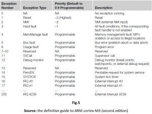

The PendSV and SVC exception
Supervisor Call (SVC) and Pendable Service Call (PendSV) are two exceptions provided for the software and operating systems. SVC is for generating system function calls. For example, an operating system may provide access to hardware through a Service call routine. Hence not allowing the user program to access hardware directly. So when a user program wants to use certain hardware, it generates the SVC exception using SVC instructions, and then the software exception handler in the operating system is executed and provides the service the user application requested. In short SVC helps to allows hardware access to unprivileged user level programs.
PendSV is usually used along with the SVC exception. Although SVC (by SVC instruction) cannot be pended (an application calling SVC will expect the required task to be done immediately), PendSV can be pended and is useful for an OS to pend an exception so that an action can be performed after other important tasks are completed. PendSV interrupt routine can be called by writing 1 to the PENDSVSET bit in the NVIC Interrupt Control State register (ICSR).
How will i start writing my own RTOS?
To start building your own RTOS you will require certain software and hardware for testing and debugging purposes. It is to be noted that there are lot of tools and hardware which can be used. But for the sake of convenience I have mentioned all tools and software used:
1. Keil Uvision:
Keil MDK is a software development solution for Arm®-based microcontrollers it includes all the components that you need to create, build, and debug embedded applications.

Here is the link to download keil Uvision 5: https://www2.keil.com/mdk5
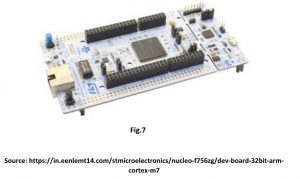
2. Any MCU with ARM cortex-m3 or higher will do the trick. For this article series I’ll be using STM32f746. It is a CORTEX-M7 based microcontroller developed by ST microelectronics. they provide an Nucleo144 development board which has an on board ST-link debugger. It should be noted that whichever board you choose it should have an on-board debugger this will help you lot to resolve errors and check your outputs.

Now that we are acquainted with the internal aspects of the operating system and our hardware. We can now jump right into creating our own project and start building our scheduler.
Author : Jayvik Desai


Jayvik Desai is a final year student of electronics and communication at Institute Of Technology . Nirma University , Ahmedabad. His major area of interest include Robotics, embedded systems, Internet Of Things and Computer Vision. He has been a part of Team Nirma Robocon during his initial year at Nirma university. He has done some projects in embedded systems and robotics as a hobby and project submissions for college. He is also active as a researcher and has been able to convert one of his project on internet of things into a publication.
Thanks for reading till end. If you liked it, Please share in your network.
You may find interesting topics at HowTo
Also subscribe Embedkari for other interesting topics. .